A 6-prong ignition switch has 6 prongs in a 9-pin plug. The 3 prongs on the top, the middle 3 pi holes are empty, and the 3 prongs on the bottom.
If your lawnmower has a similar ignition switch, you should familiarize yourself with the 6 prong ignition switch diagram so that you can troubleshoot ignition issues.
6 Prong Ignition Switch: Some Other Things
- The ignition switch has four positions: LOCK (0), ACCESSORY (I), ON (II), and START (III).
- The switch returns to the ON (II) position when you let go of the ignition switch.
- To use the built-in key, you have to remove the cover.
- Black wires are for ground wires, like the car’s electrical foundation.
- Red wires are for power wires.
- Green wires usually handle ignition duties.
- Most vehicles today have keys that have a built-in chip that communicates with the vehicle’s computer.
- Many vehicles today don’t use a key at all to turn the ignition switch.
6 Prong Ignition Switch Diagram: What Wires Go To Ignition Switch
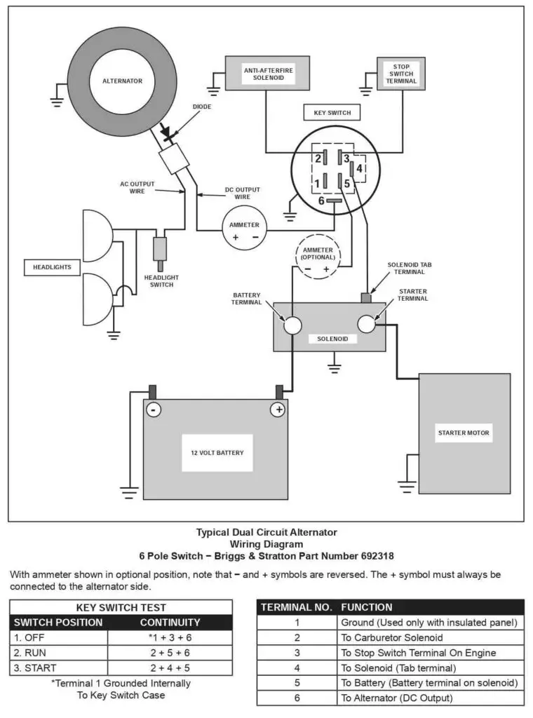
Terminal 1. Ground Terminal
The ground terminal ensures proper grounding for the switch and the entire electrical system. This terminal serves as the pathway for the current to return to the battery or power source, completing the electrical circuit.
It provides a low-resistance path for the flow of electrical current, preventing the buildup of excess voltage.
In the event of a fault or short circuit, a properly grounded system allows the excess current to flow through the ground connection, triggering circuit protection devices such as fuses or circuit breakers.
This helps prevent electrical shock hazards and reduces the risk of fire or damage to the lawnmower.
Terminal 2. Connects To The Carburetor Solenoid
The carburetor solenoid is also known as the carburetor fuel shut-off solenoid. It’s responsible for regulating the fuel supply to the carburetor based on the position of the ignition switch or the engine’s operating conditions.
When power is applied to the solenoid, it opens the fuel passage, allowing fuel to flow into the carburetor.
The number 2 terminal, as shown in the diagram above, connects the ignition system to the carburetor fuel shut-off solenoid.
The ignition switch’s terminal for the carburetor solenoid is connected to the solenoid via wiring. When the ignition switch is in the “ON” or “START” position, it completes the circuit and allows electrical current to flow to the solenoid.
Terminal 3. Connects To The Stop Switch Terminal On The Engine
Terminal 3 is designated for the stop switch or kill switch wiring. When the stop switch is engaged, it interrupts the flow of current to this terminal, causing the ignition module or coil to stop generating the spark, effectively shutting down the engine.
When the switch is in the “ON” or “run” position, it grounds the terminal and allows current to flow.
On the other hand, when the switch is in the “OFF” or “stop” position, it opens the circuit and prevents current from flowing to the terminal.
This interruption in current prevents the ignition module or coil from receiving the necessary signals to generate a spark, effectively stopping the engine’s ignition process and shutting it down.
Terminal 4. Connects To The Solenoid
This is commonly known as the “ST” or “start’” terminal. Many of you might know this, but let me clear up the confusion anyway; the solenoid we are talking about is not the carburetor solenoid we discussed above.
This one serves a whole different purpose, and for that reason, it’s connected to a different ignition terminal.
The solenoid is responsible for engaging the starter motor to crank the engine when you turn the ignition key or push the start button.
When you activate the ignition switch or start button on a lawnmower, an electrical current is sent to the solenoid. The solenoid then acts as a switch, using the current to generate a magnetic field.
This magnetic field pulls a plunger or lever inside the solenoid, which in turn connects the battery’s positive terminal to the starter motor’s electrical circuit.
By completing this circuit, the solenoid allows electrical current to flow from the battery to the starter motor, which then begins to turn the engine’s crankshaft.
Once the engine starts running, the solenoid disengages, breaking the connection between the battery and the starter motor.
The solenoid in a lawnmower serves as a crucial component that helps initiate the starting process by connecting the battery to the starter motor when you start the engine.
Terminal 5. Connects To The Battery
The number 5 terminal is the “BATT” or the “Battery” terminal. This terminal serves as the main power supply for the ignition system and other electrical components in the lawnmower.
When the ignition switch is turned to the “On” position, the battery’s positive terminal is connected to the battery terminal on the ignition switch.
This allows electrical current to flow from the battery to the ignition system, powering the spark plug and enabling the engine to start.
Other electrical components in the lawnmower, such as lights, safety features, or accessories, may also draw power from the battery through the ignition switch.
Terminal 6. Connects To The Alternator (DC Output)
The final terminal connects to the alternator. In lawnmower engines, the primary purpose of the alternator (also known as a charging coil) is to generate electrical energy to recharge the battery (if equipped) while the engine is running.
This electrical energy can also power other electrical components, such as lights, in some lawnmower models.
Ignition Switch Wiring Color Code
Color coding is a consistent and dependable method of identifying and distinguishing different electrical connections.
The use of color coding in wiring systems helps technicians, installers, and repair personnel understand and work with the wiring more easily and efficiently.
For this reason, ignition switch connections come with color-coded wiring. The commonly used color code for ignition switch wiring is as follows:
Red
The red wire commonly represents the constant power supply from the battery.
This means that the red wire connects to the positive terminal of the battery and provides a continuous flow of electrical power to the ignition switch and other electrical components in the lawnmower.
Purple
The purple wire typically connects to the starter solenoid. The purpose of this wire is to transmit the electrical current from the ignition switch, allowing it to reach the starter solenoid.
Once energized, the solenoid engages the starter motor, enabling it to turn the engine and initiate the engine starting process.
Black
The ground wire, typically colored black or sometimes green, is connected to the metal frame or chassis of the lawnmower.
Its primary function is to carry any stray or excess electrical current safely away from the electrical components and back to the battery or electrical system’s negative terminal.
Yellow
The yellow wire usually goes to the carburetor solenoid, which serves as the choke mechanism of the lawnmower engine. It carries an electric signal to the carburetor solenoid so that it turns on and allows fuel to enter the carburetor.
When the engine is turned off, the connection breaks off and the fuel remains trapped in the solenoid chamber.
Pink/Orange
The pink or orange wire you would see in an ignition system is the one that connects to the alternator. This wire delivers electricity to the alternator, enabling it to generate power and charge the battery while the engine is running.
The alternator wire also distributes electrical power to various electrical components and systems in the lawnmower.
How Does an Ignition Switch Work?
An ignition switch works like other switches. When the contacts move, it sends power to the selected circuits and cuts power to the unselected ones.
The ignition switch connects the circuit that provides voltage to the starter motor. This allows the engine to crank and eventually start.
When the ignition switch is turned on, primary current flows from the battery to the ignition switch and then to the coil primary windings. The armature turns the primary current on and off as it rotates past the pickup coil or sensor.
When the ignition switch is prompted, it activates the voltage from the battery to the ignition coil to produce the engine spark.
The ignition system sends a voltage down the HT lead to the spark plug. The high voltage causes a spark to jump between the spark plug center electrode and the earth electrode(s). The spark ignites the explosive air/fuel mixture, which expands, pushing the piston down the cylinder.
What are the Parts of an Ignition Switch?
The ignition switch is a set of electrical contacts that activate the starter. It’s usually located on the steering column.
The ignition switch has several parts, including:
- Ignition lock cylinder and key
- Ignition lock cylinder retaining pin
- Ignition plate, lever, and button kit
- Spring-loaded plunger
- Switch disc with détentes.
Final Words
It’s important to understand a 6 prong ignition switch diagram for repairing or maintaining a mower that features a 6-prong ignition switch.
In this piece, I wanted to shed light on the intricate wiring connections and their specific roles within the ignition system. With this knowledge, lawnmower owners can confidently address ignition switch problems.

- 15 Common John Deere LT155 Problems (Quick Guide) - November 26, 2023
- John Deere LX277 Problems (360 Guidelines) - September 22, 2023
- John Deere 3025E Problems (Reasons + Solutions) - September 19, 2023